Procurar 2 Fases Nema23 Sistema De Motor De Passo De Malha Fechada, Motor Deslizante Do Laço Fechado De Baixo Preço Para Nema23 57Mm, 2 Servo Motor Deslizante Híbrido Do Laço Próximo De Nema 23 Da Fase Com Motorista no diretório Industry Directory, fabricante / fornecedor / Fábrica confiável a partir de China
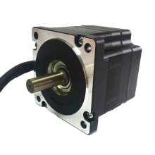

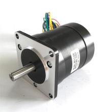
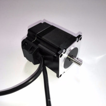
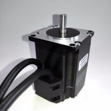
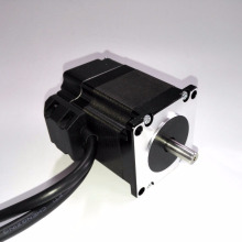
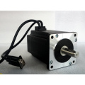
Modelo: JK57HS
 \ n \ n \ n
  \ n \ n \ n \ n Descrição do Produto Recursos: \ n 1. Encerramento fechado, elimina a perda de sincronização \ n2. Faixa de operação mais ampla - maior torque e maior velocidade \ n3. Aquecimento do motor reduzido e mais eficiente \ n4 .Movimento suave e ruído de motor muito baixo \ n 5.Não precisa de uma margem de torque alta \ n 6.Sem Tuning e sempre estável \ n 7.Rápida resposta, sem demora e quase sem tempo de espera \ n 8.Bigh torque em início e baixa velocidade, alta rigidez na paralisação \ n 9.Custo menor \ n 10.20-50V, 8.0A Pico, Sem ajuste, Perda nula da Sincronização \ n \ n Especificações elétricas (Tj = 25oC / 77oF) \ n \ n
 Parameters |
HBS57 |
|||
Min |
Typical |
Max |
Unit |
|
Output current |
0 |
- |
8.0 (Peak) |
A |
Input voltage |
20 |
36 |
50 |
VDC |
Logic signal current |
7 |
10 |
16 |
mA |
Pulse input frequency |
0 |
- |
200 |
kHz |
Isolation resistance |
500 |
|
|
MΩ |
Control Signal Connector - Screw Terminal |
|
||||||
Pin |
Name |
I/O |
Description |
|
|||
1 |
PUL+ |
I |
Pulse signal: In single pulse (pulse/direction) mode, this input represents pulse signal, each rising or falling edge active (software configurable, see hybrid servo software operational manual for more detail); In double pulse mode (software configurable), this input represents clockwise (CW) pulse, active both at high level and low level.4-5V when PUL-HIGH, 0-0.5V when PUL-LOW. For reliable response, pulse width should be longer than 10μs. Series connect resistors for current-limiting when +12V or +24V used. The same as DIR and ENA signal. |
|
|||
2 |
PUL- |
I |
|
||||
3 |
DIR+ |
I |
Direction Signal: In single-pulse mode, this signal has low/high voltage levels, representing two directions of motor rotation.In double-pulse mode (software configurable), this signal is counter-clock (CCW) pulse, active both at high level and low level.For reliable motion response, DIR signal should be ahead of PUL signal by 5μs at least. 4-5V when DIR-HIGH, 0-0.5V when DIR-LOW. Please note that rotation direction is also related to motor-driver wiring match. Exchanging the connection of two wires for a coil to the driver will reverse motion direction. The direction signal’s polarity is software configurable. |
|
|||
4 |
DIR- |
I |
|
||||
5 |
ENA+ |
I |
Enable signal: This signal is used for enabling/disabling the driver. In default, high level (NPN control signal) for enabling the driver and low level for disabling the driver. Usually left UNCONNECTED (ENABLED). Please note that PNP and Differential control signals are on the contrary, namely Low level for enabling. The active level of ENA signal is software configurable. |
|
|||
6 |
ENA- |
I |
|
||||
7 |
ALM+ |
O |
AlarmSignal: OC output signal,active when one of the following protection is activated: over-voltage, over current, short circuit and position following error. This port can sink or source 20mA current at 24V. In default, the resistance between ALM+ and ALM- is low impedance in normal operation and become high when HBS57 goes into error. The active level of alarm signal is software configurable. See Hybrid servo software operational manual for more detail. |
|
|||
8 |
ALM- |
O |
|
||||
Encoder Feedback Connector – DSub15 Female | |||||||
Pin |
Name |
I/O |
Description |
||||
1 |
EA+ |
I |
Encoder channel A+ input |
||||
2 |
EB+ |
I |
Encoder channel B+ input |
||||
3 |
EGD |
GND |
Signal ground |
||||
4 |
HW |
I |
Reserved |
||||
5 |
HU |
I |
Reserved |
||||
6 |
FG |
GND |
Ground terminal for shielded |
||||
7 |
EZ+ |
I |
Reserved |
||||
8 |
EZ- |
I |
Reserved |
||||
9 |
HV |
I |
Reserved |
||||
10 |
NC |
- |
Not Connected |
||||
11 |
EA- |
I |
Encoder channel A- input |
||||
12 |
EB- |
I |
Encoder channel B- input |
||||
13 |
VCC |
O |
+5V @ 100 mA max. |
||||
14 |
NC |
- |
Not Connected |
||||
15 |
NC |
- |
Not Connected |
||||
Power and Motor Connector- Screw Terminal | |||
Pin |
Name |
I/O |
Description |
1 |
U |
O |
Motor Phase U |
2 |
V |
O |
Motor Phase V- |
3 |
W |
O |
Motor Phase W |
4 |
+Vdc |
I |
Power Supply Input (Positive) 20-45VDC recommended, leaving rooms for voltage fluctuation and back-EMF. |
5 |
GND |
GND |
Power Ground (Negative) |
 \ n \ n \ n Exposição:
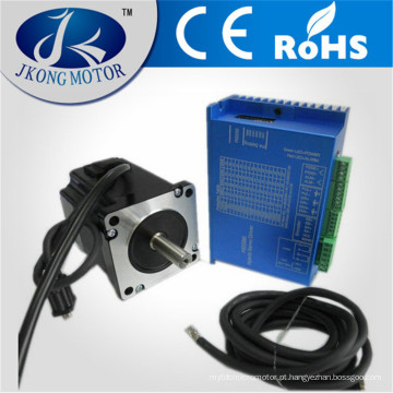
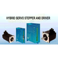
  \ n \ n \ n \ n \ n Nossos serviços \ n Nós também fornecemos Kits de motor de passo, motor de passo linear, motor de corrente contínua, motor de passo de freio, motor de passo com codificador, acoplamento flexível, Pully, fonte de alimentação, etc. .. \ n \ n
Grupo de Produto : Fechar o motor de passo de loop > NEMA23-57mm NEMA24-60mm motor de passo